Frequently Asked Questions
Generators
For use in Spring, Summer & Autumn months on either Petrol or Diesel Generators we would suggest that 10w30 is most suited but can be sometimes difficult to source, In which case we would recommend you purchase 10w40which would be absolutely fine.
If you or your customer intends operating your Generator at very low temperatures usually Winter months then we would recommend using 5w30.
1. Turn the front panel engine switch ON (middle position).
2. Turn the battery switch ON.
3. Push and hold the programming button on left side of the panel next to the red light (located on the back left side of the panel) approximately three seconds until the light turns on.
4. Push and release the STOP button on the remote. The red light blinks once to erase the remote program. If you have a second remote, press the STOP button on it as well.
5. Push and release the START button. The red light blinks once to program the remote. If you have an additional remote, press the START button on it as well.
6. Push and hold the programming button approximately three seconds until the red light turns off.
Watch this video
Most motor-driven products that you will connect to your generator need extra watts when they start, this is known as starting watts.
The Starting Watts listed on your generator is the wattage the generator can output for an average of 6 seconds (Inverter) or 10 minutes (Open Frame Type).
Once this period is over, and if the wattage has not reduced the Overload Protection will activate and the generator will trip using the following methods circuit breaker (frame type) and flashing overload light (Inverter), if this happens the power (wattage) needs to reduced or disconnected immediately and the generator needs to be reset by stopping the generator and turning everything to the ‘OFF’ position and leaving for minimum 2 minutes (Inverter Only).
The Maximum Watts listed on your generator is the MAX watts output the generator can run at – however it is not recommended to run your generator at the maximum watts for periods more than average 5 minutes (Inverter) and 60 minutes (Open Frame Type). Once this period is over, and if the wattage has not reduced the Overload Protection will activate and the generator will trip using the following methods circuit breaker (frame type) and flashing overload light (Inverter), if this happens the power (wattage) needs to reduced or disconnected immediately and the generator needs to be reset by stopping the generator and turning everything to the ‘OFF’ position and leaving for minimum 2 minutes. While working in the max zone on an Inverter you will have solid red overload light this is normal.
The most common reason your dual fuel inverter isn't starting on propane is because the black bracket (Supplied) that connects to the pressure reducing valve hasn't been installed and the valve is left in a horizontal or dangling down position causing the diaphragm to stick or not move.
If this happens you need to install the black plastic bracket supplied and clip it to the handle so that the reducing valve is in a upright position and retry starting.

If the generator still isn't starting, the diaphragm may need to be adjusted. To do this turn on the bottle (gas flow) and using pin or needle gently place it on the small hole on the front of the reducing valve, press gently for approx. 10-15 secs and then recoil again to start.

If the problem persists then contact our technical team on 01942 715407 Option 2 for further assistance.
If you have a 82001i-DF and you are struggling to start it from cold use the following method:
- ENSURE pressure reducing valve is assembled in its black holder and clipped to the handle in position
- Turn the dial to approx. 9 o’clock position part way between ‘CHOKE’ and ‘RUN’
- Gently pull 2 or 3 times to prime
- Recoil a number of times to start
- Turn dial to ‘RUN’ position and allow engine increase RPM
Frame type models use the following method:
- Move Choke lever part way between ‘CHOKE’ and ‘RUN’
- Turn on fuel valve and gently recoil 2 or 3 time to prime
- Recoil a number of times to start
- Move choke lever to the ‘RUN’ position and allow engine RPM to increase
If electric start repeat process using the ignition switch instead of the manual recoil assembly, ENSURE you have sufficient battery power to crank the engine.
If you have trouble starting your 92001i Inverter Generator please follow these steps:
1: Check Oil Level
Check the oil dipstick to see if it meets the requirement (see manual for more info).
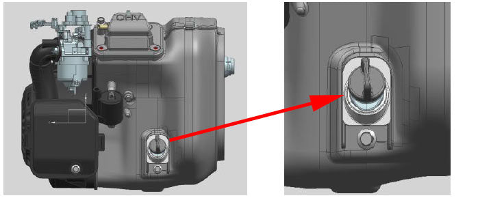
2: Check these switches

A: Ensure this switch is turned ON (horizontal).
B: Ensure the pressure relief valve is turned ON.
3: Check the Spark Plug

Ensure the spark plug gap is as per the manual and no fouling/wet areas on the electrode. Too much choke leads to spark plug fouling /engine flooding due to the lack of incoming air. This will cause the engine not to start.
4: Check the Carburetor

Check the choke and throttle. Push the choke cable to see if the choke valve is rotatable. Ensure the throttle valve is open.
If the choke cable is loose, reassemble it. If the throttle is closed (might happen in the case of an abnormal flameout), manually open the throttle valve.
5: Check the Fuel Line

Remove the fuel drain bolt, open the fuel switch, and observe whether any fuel is flowing out of the carburetor. If no fuel, check fuel supply line for any kinks or abnormatlities.
6: Check the Control Panel Wires

Tie up the ground wire (black one) to the flameout micro switch wire harness (green one and black one) and the igniter connector. As shown in the left pic, when the wire harness is loose, it might interfere with the flameout micro switch (forcing it to close), resulting in no start.
This video will run you through the process.
Its a very simply clip in operation best explained by the video below:
General
Noise Level Information
The decibel which is normally abbreviated dBA is the unit used to measure the intensity of a sound. The human ear is incredibly sensitive, a person's ears can distinguish between wide ranging sounds such brushing their fingers on a notepad to the loudest explosion or Jet aircraft. To put these differences into perspective a jet aircraft is 1,000,000,000,000 times more louder than the quietest audible sound.
Looking on the decibel scale, the smallest audible sound which is near silence registers at 0 dB. An increase of 10 decibels equates to a 10 fold increase in noise to your ear.
Important Point! Generators are measured and compared within the industry @ 7 metres.
To comply with EEC regulations all generators have to be marked in LWA this is a different measurement of sound which is taken from a different distance. For an example our quiet Champion 71001i is rated at its lowest at 53 dBA @ 7 metres. On the LWA scale this would equate to approx 86-88 decibels. Please beware of this as all products have LWA marked on them, many do not have the industry rated @ 7 metres level.
Here are some common sounds and their decibel ratings:
| Sound Levels Chart | ||
|---|---|---|
| 120 | Pneumatic drill | |
| 110 | Noisy factory | |
| 100 | Inside underground train | |
| 90 | Inside bus | |
| 80 | Average traffic on main road (at kerb) | |
| 70 | Normal Conversation (at 1m) | |
| 60 | Typical business office | |
| 50 | Living room in suburban area | |
| 40 | Library | |
| 30 | Bedroom at night | |
| 20 | Insulated broadcasting studio | |
| 10 | Threshold of hearing | |
| 0 dB | Silence | |
| Note: A 10 dB increase represents a doubling in loudness to the ear. | ||
| More Sound Info | |
|---|---|
| 190 dBA | Heavy weapons, 10 m behind the weapon (maximum level) |
| 180 dBA | Toy pistol fired close to ear (maximum level) |
| 170 dBA | Slap on the ear, fire cracker explodes on shoulder, small arms at a distance of 50 cm (maximum level) |
| 160 dBA | Hammer stroke on brass tubing or steel plate at 1 m distance, airbag deployment very close at a distance of 30 cm (maximum level) |
| 150 dBA | Hammer stroke in a smithy at 5 m distance (maximum level) |
| 130 dBA | Loud hand clapping at 1 m distance (maximum level) |
| 120 dBA | Whistle at 1 m distance, test run of a jet at 15 m distance |
| Threshold of pain, above this fast-acting hearing damage in short action is possible. | |
| 115 dBA | Take-off sound of planes at 10 m distance |
| 110 dBA | Siren at 10 m distance, frequent sound level in discotheques and close to loudspeakers at rock concerts, violin close to the ear of an orchestra musicians (maximum level) |
| 105 dBA | Chain saw at 1 m distance, banging car door at 1 m distance (maximum level), racing car at 40 m distance, possible level with music head phones |
| 100 dBA | Frequent level with music via head phones, jack hammer at 10 m distance |
| 95 dBA | Loud crying, hand circular saw at 1 m distance |
| 90 dBA | Petrol Lawnmower |
| 85 dBA | 2-stroke chain-saw at 10 m distance, loud WC flush at 1 m distance |
| 80 dBA | Very loud traffic noise of passing lorries at 7.5 m distance, high traffic on an expressway at 25 m distance |
| 75 dBA | Passing car at 7.5 m distance, un-silenced wood shredder at 10 m distance |
| 70 dBA | Level close to a main road by day, quiet hair dryer at 1 m distance to ear |
| 65 dBA | Normal Conversation |
| 60 dBA | |
| 55 dBA | Low volume of radio or TV at 1 m distance, noisy vacuum cleaner at 10 m distance |
| 50 dBA | Refrigerator at 1 m distance, bird twitter outside at 15 m distance |
| 45 dBA | Noise of normal living; talking, or radio in the background |
| 35 dBA | Very quiet room fan at low speed at 1 m distance |
| 25 dBA | Sound of breathing at 1 m distance |
| 0 dBA | Auditory threshold |
The generator is configured differently to the mains supply. The generator has a 'floating earth' whilst the mains has an earthed neutral.
Although it is recommended to use a personal power breaker (RCD) from the mains, for the majority of cases, it is not necessary to use one with a generator. The generators are safe as they are designed to work without a RCD. Personal power breakers are designed to operate from the mains. If one is to be used with a generator, then it is necessary to modify the generator so that it is configured in the same way as the mains.
This is a relatively simple modification for a qualified electrician involving adding a link wire from the neutral terminal to the earth terminal. However, once the generator has been modified, it is necessary to then always use a personal power breaker and to also always use an earth spike, which connects between the generator frame and the ground. Since this is difficult to ensure, it is generally recommended not to modify the generator.
Please note the following precautions:
It is vital that the generator is completely isolated from the mains supply.
This ensures that the generator is not attempting to power up the whole neighborhood, but also ensures that it does not electrocute a utility worker trying to restore the mains supply. To achieve this, a double-pole, break-before-make, changeover switch must be installed by a qualified electrician. This should be fitted between the electricity meter and the building consumer unit. The switch connects the building to either the mains supply or to a lead which can be plugged into the generator.
Configure the Generator to use a RCD:
Most buildings now have an RCD built into the consumer unit. This is configured to operate from the mains supply with an earthed neutral, and not from a generator with a floating earth. To utilize this protection device, it is necessary to modify the generator so that it is configured in the same way as the mains supply. This is a simple modification for a qualified electrician, involving adding a link wire from the neutral terminal to the earth terminal. It is recommended to make this connection in the plug that is to be used to connect to the generator. This ensures that the generator is unmodified when it is disconnected from the house, and therefore remains safe.
The plug should be labeled ?Do not connect to mains: Neutral-Earth link fitted?.
The lead between the generator and the transfer switch is not protected by the RCD, it is therefore recommended to use a steel armored cable for this connection.;
A local low-impedance earth spike needs to be installed.
There are 3 types of electrical:
1) Real Power, measured in Watts (W).
This is the power drawn by a resistive load, e.g. a heater element in a kettle, and has a power factor of 1. (unity power factor, cos F=1, 1.0pf or pf=1)
2) Reactive Power, measured in Volt Amperes reactive (VAr?s).
This is the power drawn by a reactive load (a load with a winding around a core), e.g. an electro-magnet, and has a power factor of 0. (zero power factor, cos F =0, 0pf or pf=0)
3) Apparent Power, measured in Volt Amperes (VA).
Many loads have a combination of resistive and reactive elements. (in fact it is not possible to produce a purely inductive load, since the wire used to form the windings has a resistance). This combination of elements means that both real power (W) and reactive power (VAr) are drawn together.
The proportion of Real Power to Reactive Power is defined as the power factor. [Nearly all resistive load (e.g. Universal motor used in hand tools) then power factor 0.95 to 1.0, nearly all inductive load then power factor ~ 0.3] The vast majority of single-phase loads have power factors approaching 1.
Therefore, single-phase generator power ratings are taken at power factor =1, and are consequently in Watts (W) or kilo Watts (kW), where 1 kW = 1000 W.
Three-phase loads tend to have lower power factors, approaching 0.8, therefore, three phase generator power ratings are taken at power factor =0.8 and are in VA or kVA.
There is obviously a relationship between real power, reactive power, apparent power and power factor?
i) Apparent Power (VA) = ? [(real power (W))2 + (reactive power (VAr))2] And
ii) Power factor = Real Power (W) Apparent Power (VA)
Therefore?Apparent Power (VA) x Power factor = Real power (W)
If the Power factor =1, then all the Power is real, and Apparent Power (VA) = Real Power (W) (W = VA @ 1.0 pf)
For a single-phase generator, the rating should be at 1.0 pf, in which case Watts = Volt Amperes. But, for a three-phase generator the rating is at 0.8pf.
This is where confusion can arise!
Example. A three-phase generator has a continuous rating of 5 kVA at 0.8 pf. Now, at this rated load, the Real power (kW) will be ?Real Power (kW) = Apparent Power (kVA) x Power factorReal Power = 5 x 0.8 = 4kW
This means that a generator producing 5kVA at 0.8pf is actually producing 4 kW of Real power, but it is also producing some reactive power.
From i)? 5000 VA = ? [( 4000 W)2 + ( Reactive Power)2] Reactive Power = 3000 VAr?s
It is this combination of 4kW of real power and 3kVAr?s of reactive power that has defined the limit for the generator rating. If the same generator was loaded with a resistive load only, then it may be capable of more than 4kW, however, there is no formula that can be used to find this limit from the 0.8pf rating. It can only be found through testing of each machine. Similarly, a single-phase generator rated at 4kW, cannot be expected to produce 5kVA at 0.8pf !
The output from the mains of your house and a generator are not the same. The generator output is less stable.
The speed of the engine driving is controlled on the amount of load placed on the generator. The speed drops as the load is increased. The frequency of the output voltage is directly dependent on the engine speed; therefore, the frequency of the output varies with load. In addition, the output voltage will vary with load, and with temperature.
The output voltage of most standard generators will remain within 230V +/- 10% from no load up to the rated load current quoted on the information plate. This is the guaranteed range of voltage supplied from the mains utilities. The frequency of the output voltage will vary typically from 53Hz at no load to 49Hz at rated load current, whereas the mains supply is unlikely to vary by more than 0.1 Hz.
Most electronic equipment is designed to cope with these fluctuations. However, we recommended to ask the equipment supplier whether their equipment is suitable to be operated from a portable generator. As a generator runs out of fuel, the engine is likely to surge.
(To avoid this affecting electronic equipment an Uninterruptible Power Supply (UPS) can be used. These are typically sold for use with computers so that data is not lost in the event of a power cut).
Inverters Produces Power Stability
Computers and power-sensitive testing equipment require electrical current that is consistent and has a stable \"sine wave\" or signal. Your lights and other basic home equipment can handle fluctuations from a AC fluctuation.
However, if your computer was being powered by a generator and the voltage fluctuated, chances are the computer would shut down or at least interrupt the program you were working in. In order to overcome this problem, a revolutionary form of inverter technology was developed. This process results in a sine wave equal to or better than the current from your household AC wall outlet.
This means that, you can operate a computer or laptop direct from a inverter generator.
What is AVR?
AVR bascially gives the same output as an inverter machine, generators equipped with AVR (Automatic Voltage Regulator), this feature limits the variation of the voltage of your generator to + or - 2 %. With a generator equipped with AVR you can run sensitive equipment such as computers.
There are many different designs of motor, each with different characteristics.
Some motors, e.g. Induction type motors (capacitor start / capacitor run) require additional current to start them, therefore requiring a larger generator. Motors fitted to hand tools generally do not require any additional start-up current. Consequently, it is recommended to ask the supplier of the equipment that you wish to run whether it requires additional start-up current.
As a rough guide only, allow for a generator that has a continuous rating of 2 ? to 3 times the motor POWER rating. Motors can be rated in kW or HP. To convert HP to kW, multiply by ?.
E.g. What generator to run a 3HP motor? 3HP = 3 x ? = 2.25kW. This Induction motor would require a generator of between; (2 ? x 2.25) = 5.625kW and ? (3 x 2.25) = 6.75kW
A welder is rated by its output current. To estimate its input power, divide the output rating by 30.
E.g. A 130A welder will have an input requirement of approximately 130/30=4.3kW.
A 200A welder will have an input requirement of approximately 200/30=6.7kW.
This is only an estimate; therefore, it is recommended to choose a generator of the next size up. However, bear in mind, that many users will not actually require the full capacity of their welder, a smaller generator would still operate the welder, but would limit the welding current.
When a generator is required for a power source there are two types of installation. Most people can only install any generator in a Class I installation constituting in the generator installation to be used with out an earth supply. This is perfectly OK if using equipment that have very low conductivity like power tools, other power equipment and some house hold appliances.
However if a generator is bought for a power source for a house, barn or cabin etc then usually they are required by law to install it in a Class II which means a direct earth is required from the generator to main RCD board this can be done by simply using a high quality earthing rod from deep in the ground to the generators earthing point. This type of installation should be carried out by a qualified electrician and the system has to be professionally installed for the safety of the user. Failing to use this method could result in damage to generator and also many types of equipment being powered and in worse case injury to the user.
The generator is configured differently to the mains supply. The generator has a ?floating earth?, whilst the mains has an earthed neutral.
Although it is recommended to use a personal power breaker (RCD) from the mains, for the majority of cases, it is not necessary to use one with a generator. The generators are safe as they are designed to work without a RCD. Personal power breakers are designed to operate from the mains. If one is to be used with a generator, then it is necessary to modify the generator so that it is configured in the same way as the mains.
This is a relatively simple modification for a qualified electrician involving adding a link wire from the neutral terminal to the earth terminal. However, once the generator has been modified, it is necessary to then always use a personal power breaker and to also always use an earth spike, which connects between the generator frame and the ground. Since this is difficult to ensure, it is generally recommended not to modify the generator.
Single-phase power is:
- Used in most homes around the world.
- Able to supply ample power for most smaller customers, including homes and small, non-industrial businesses.
- Adequate for running motors up to about 5 horsepower; a single-phase motor draws significantly more current than the equivalent 3-phase motor, making 3-phase power a more efficient choice for industrial applications.
With the wave form of single-phase power, when the wave passes through zero, the power supplied at that moment is zero. In the U.S., the wave cycles 60 times per second.
3-phase power is:
- Common in large businesses, as well as industry and manufacturing.
- Increasingly popular in power-hungry, high-density data centers.
- Expensive to convert from an existing single-phase installation, but 3-phase allows for smaller, less expensive wiring and lower voltages, making it safer and less expensive to run.
- Highly efficient for equipment designed to run on 3-phase.
3-phase power has 3 distinct wave cycles that overlap. Each phase reaches its peak 120 degrees apart from the others so the level of power supplied remains consistent.
To illustrate the difference between single-phase and 3-phase, imagine a lone paddler in a canoe. He can only move himself forward while his paddle moves through the water. When he lifts the paddle out of the water to prepare for the next stroke, the power supplied to the canoe is zero.
Now picture the same canoe with three paddlers. If their strokes are synchronized so each is separated by 1/3 of a stroke cycle, the canoe receives constant and consistent propulsion across the water. More power is supplied and the canoe moves across the water more smoothly and efficiently.
How do single and three phase systems work?
Single-phase systems use alternating current electric power in which the voltage and current flow changes in magnitude and direction in a cyclical fashion, typically 60 times per second. In the U.S., single-phase voltage is 120 Volts, while several other countries use 230 Volts as the standard. A variation of single phase, called split phase, is also in effect in the U.S. where two wires carry 120 Volts each with a common neutral thus providing the option to hook up high power loads to the 240 Volt power circuit and low power loads to 120 Volt power circuit.
In three-phase systems, the power circuit combines three alternating currents that vary in phase by 120 degrees. As a result, the power would never drop to zero, making it possible to carry more load. In a typical 120 Volt power arrangement, this is equivalent to three 120 Volt single-phase power circuits and one 208 Volt power circuit.
What are the benefits of three-phase systems over single-phase?
The cost to install and maintain three-phase systems is substantially lower than that of single-phase systems. Three-phase systems use substantially less conductor material than that of single-phase systems ? about 25 percent less for the same amount of power delivered. For the same amount of time, three-phase power lines can carry more power than that of single-phase power lines at a reduced cost. In addition to reduction in copper, a three-phase system requires fewer circuit breaker pole positions for 208 Volt loads. The power delivered is almost constant in three-phase power circuits, making them ideal candidates for transmission lines, power grids, and data centers.
Three phase generators draw significantly lower amps than a single phase because they use a (Coefficent 1.733). Three phase Equation is watts (W)/voltage (V)/(Coeffient 1.733)=(A)amps.
Dual voltage generators only produce full power on larger output voltage due to the wiring configuration of the alternator. Single phase or lower power only use two winding of the 4 available on the alternator so usually resulting off a power reduction 40-50% from the quoted continuous output power. In a case where the generator is three phase and also single phase the maximum value always goes to the greater number eg 415v in this case leaving the single phase to 40-50% lower output.
This chart will help you calculate the sound power.
| Sound power | Theoretical average sound pressure level [dB(A)] | |||||||||
|---|---|---|---|---|---|---|---|---|---|---|
| LWA | 1m | 3m | 4m | 5m | 7m | 8m | 9m | 15m | 16m | 30.5m |
| 80 | 72 | 62.5 | 60 | 58 | 55.1 | 54 | 53 | 48.5 | 47.9 | 42.3 |
| 85 | 77 | 67.5 | 65 | 63 | 60.1 | 59 | 58 | 53.5 | 52.9 | 47.3 |
| 90 | 82 | 72.5 | 70 | 68 | 65.1 | 64 | 63 | 58.5 | 57.9 | 52.3 |
| 95 | 87 | 77.5 | 75 | 73 | 70.1 | 69 | 68 | 63.5 | 62.9 | 57.3 |
| 100 | 92 | 82.5 | 80 | 78 | 75.1 | 74 | 73 | 68.5 | 67.9 | 62.3 |
| 105 | 97 | 87.5 | 85 | 83 | 80.1 | 79 | 78 | 73.5 | 72.9 | 67.3 |
| 110 | 102 | 92.5 | 90 | 88 | 85.1 | 84 | 83 | 78.5 | 77.9 | 72.3 |
| 115 | 107 | 97.5 | 95 | 93 | 90.1 | 89 | 88 | 83.5 | 82.9 | 77.3 |
| 120 | 112 | 102.5 | 100 | 98 | 95.1 | 94 | 93 | 88.5 | 87.9 | 82.3 |
| reduction | 8 | 17.5 | 20 | 22 | 24.9 | 26 | 27 | 31.5 | 32.1 | 37.7 |
LWA95 corresponds to 70dB(A) at 7m from the noise source.
72dB(A) at 7m from the noise source corresponds to LWA97.
Here is standard chart of the different oil types, most common used in the UK is 10w30 or 10w40. The main differences in the oil types are the operating temperature a smaller first figure usually means a lower starting temperature and larger second figure usually means high operating temperature.
If you are unsure of the oil type for your generator a good rule of thumb is first determine your countries climate!!! Do you have very cold winters and very hot summers, your oil type should be based on the climate the generator is going to be use in for example if it is mainly winter then a lower starting temperature oil is recommend or if it going to be summer months then a higher operating oil type is recommended.

Oil types usually come in part synthetic or fully synthetic and the cost varies, More expensive branded oil are no better than premium branded oil they are more or less the same product but some more expensive brands do have additional additives. Any part or fully synthetic oil for a generator will be perfectly OK as long as the oil changes are regular and it line with the maintenance schedule.
Below is a rough guide to Champion Generators fuel consumption. All figures are taken from a test environment in the factory, figures quoted are accurate estimations at the time of test and will vary.
| Generator | Fuel | Load without Eco | ||||
|---|---|---|---|---|---|---|
| 25% | 50% | 75% | 100% | |||
| 73001i / 73001i-P | Petrol | L/Hour | 0.75 | 0.92 | ND | 1.6 |
| 73001i-DF | Petrol | L/Hour | 0.88 | 1.2 | 1.56 | 1.97 |
| LPG | Kg/hour | 0.8 | 0.8 | 1 | 1.26 | |
| 82001i | Petrol | L/Hour | 0.38 | 62.5%: 0.71 |
93.75%: 1 |
1.05 |
| 82001i-DF | Petrol | L/Hour | 0.38 | 62.5%: 0.71 |
93.75%: 1 |
1.05 |
| LPG | Kg/hour | 0.27 | 62.5%: 0.52 |
93.75%: 0.65 |
0.554 | |
| 92001i | Petrol | L/Hour | 0.47 | 0.69 | 0.95 | 1.17 |
| 92001i-DF | Petrol | L/Hour | 0.47 | 0.69 | 0.95 | 1.17 |
| LPG | Kg/hour | 0.33 | 0.43 | ND | 0.65 | |
| CPG4000E1 | Petrol | L/Hour | ND | 1.58 | 2.03 | 2.6 |
| CPG4000DHY | Petrol | L/Hour | 0.79 | 1.2 | 1.70 | 2.0 |
| 500559/60 | Petrol | L/Hour | ND | 1.46 | 1.73 | 2.24 |
| CPG6500E2 | Petrol | L/Hour | ND | 2.65 | 3.29 | 3.96 |
| CPG7500E2-DF | Petrol | L/Hour | ND | 2.8 | 3.6 | 4.18 |
| LPG | Kg/hour | ND | 2.64 | 2.94 | 3.4 | |
| CPG9000E2 | Petrol | L/Hour | ND | 2.80 | 3.53 | 4.14 |
ND = No Data
When you purchased your portable generator, you either filled it up with petrol and oil to give it a test run or you waited until you actually needed it. Once you tested it or used it the first time, you probably put it away and moved on.
Has a month or more passed since you put your generator away? If so, the gas left in the carburetor can start to go bad. Gasoline that has not been treated with fuel stabilizer can gum up the carburetor creating blockages that will affect the engine's performance.
Blockage warning signs to watch for:
- You're only able to run the machine on choke.
- Surging.
- Your generator won't start at all.
When an outage occurs, you pull your generator out of storage, trusting it to get your lights back on, keep your food from spoiling, and heat or cool your home. What if it doesn't work? What then?
If your generator was stored improperly, it may not be able to come through for you.
Just like your generator, your log splitter, snow blower, and other petrol-powered products need to be stored properly. Whether you need to keep the power on, split logs to stay warm during cold days and nights, or clear snow after a heavy winter storm, it's important to keep the fuel fresh in any of your petrol-powered products so they're ready to go when you are.
Take a little bit of extra time now and go through this safe storage checklist to ensure your peace of mind later.
Use the Right Type of Fuel: We recommend unleaded petrol with an ethanol content of 10% or less. It's perfectly fine to use 85 to 91 octane fuels. The difference between them won't be noticeable. Using non-ethanol fuel is beneficial since it reduces fuel storage issues. Visit www.Pure-Gas.org to find a station that offers this kind of fuel.
Add Fuel Stabilizer: Storing your generator without the addition of fuel stabilizer means the petrol can go bad within a month, causing major problems. Using fuel stabilizer can help extend the petrol's lifespan for up to 24 months. If you do have older fuel sitting in the carburetor, we recommend that you run it at least once a month for about 15 minutes to prevent any older fuel from corroding it. You can get stabilizers at your local auto parts store or online.
Clean or Replace Your Carburetor: Bad fuel produces debris that prevents fuel from flowing the way it should. If your generator has been stored improperly with petrol in the fuel tank or carburetor, all the fuel must be drained and the carburetor has to be cleaned to remove the debris and clear up blockages so you can use your generator safely.
Want to skip the cleaning process? Replace your unit's carburetor and your generator will fire right up.
If you did store your generator properly by draining the fuel tank and carburetor according to your owner's manual, great! You have a much easier job ahead of you.
Removal from Storage: Take your generator out of storage and place it outside.
Add Fresh Fuel: The first thing you'll need to do is add fresh, regular octane fuel. Make sure you don't overfill the tank so you can allow for fuel expansion.
Check for Fuel Leaks: Next, you're going to want to check for fuel leaks. Make sure your engine switch is off, then, turn your fuel valve on. Wait five minutes and then check the carburetor and air filter areas for leaks. If you do happen to discover a leak, you'll need to disassemble your carburetor to clean it or replace it.
Check the Oil: If you don't find any leaks, you can go ahead and turn your fuel valve to off, use a dipstick to check the oil level, and add fresh oil if necessary.
Check the Air Filter: Next, take a look at your air filter and make sure there are no obstructions like bugs or cobwebs. Remove any obstructions you find and clean and replace the air filter according to your owner's manual.
That's it!
Fresh fuel, no leaks, fresh oil, clean air filter, and you're good to go.
The next time you're ready to store your generator, log splitter, snow blower, or other petrol-powered product, resist the urge to just put it away quickly because you have other things to do. During an emergency, you may not have the luxury of time to complete this checklist properly.
Take the time now to do it right, and you'll save yourself time and hassle later. Your future self will thank you!
Pressure Washers
The usual cause of low pressure is as follows:
Male and female hose adapters not connecting properly.
Check connection between both male and female hose adapters. Remove male from pump assembly and mate into female and turn on water supply. If low or no pressure adapters need to be replaced. It recommended that a brass female hose adapter is used otherwise plastic and brass doesn't always mate correctly.

Blocked nozzles
Check for blockages in nozzles with needle or pin. (Refer to manual)
Air lock in pump
Disconnect 26ft outlet hose from pump, connect inlet water supply and you should get a flow through the pump, start the engine and repressurise the pump. Stop engine reconnect up outlet hose and purge the air out of the gun by pressing the trigger and repeat the start up process to regain pressure.
Damage or broken pressure spring
Remove 14mm bolt to first access the steel ball bearing, using a magnet remove ball bearing and pressure spring, check and replace spring if required. Put back together and retest washer pressure. If problem persist then there may be an issue with the pump or gearbox of the assembly. Contact us on +44 (0)1942 715407 option 2 for replacement parts.
Below is a illustration of where to find and check the pressure spring.

- Opens in a new window.